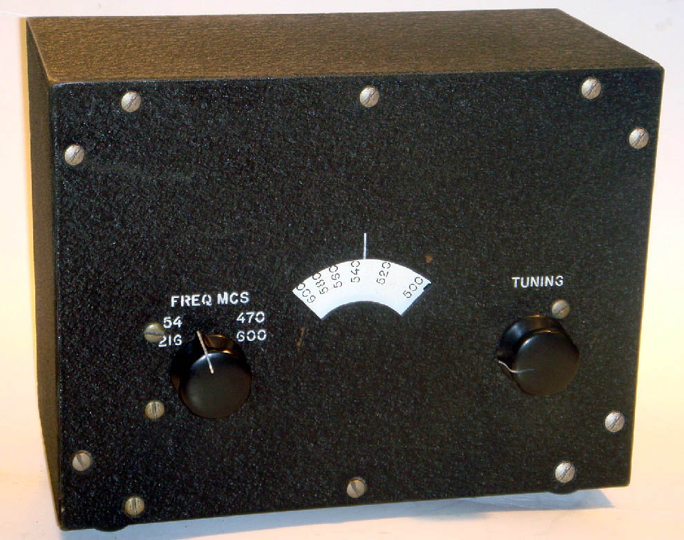
A
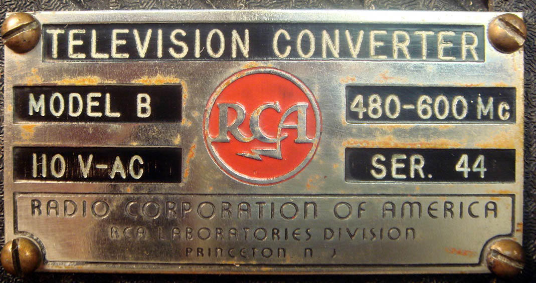
field test of ultra-high-frequency television was conducted
by RCA and NBC in the Washington, DC area during the fall of
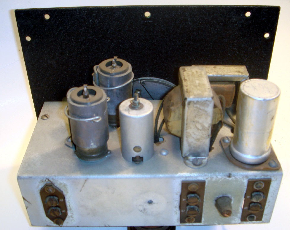
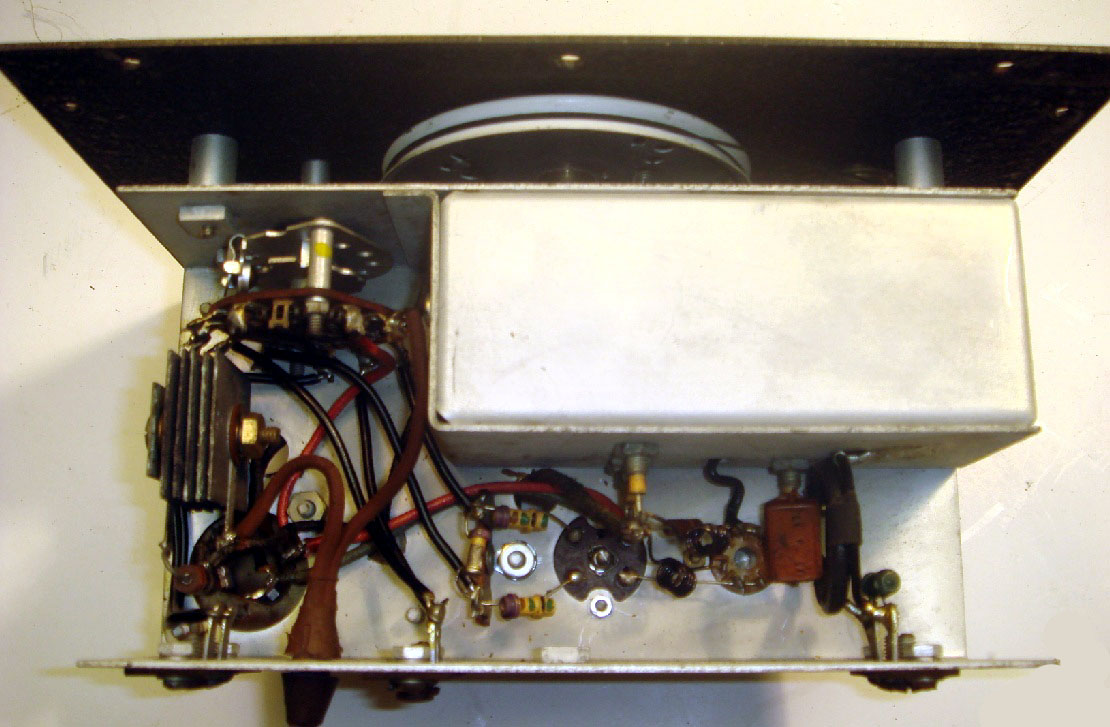
1948. Two types of converters were constructed, shown above
is one of the Model B converters used in the test.
A
picture transmitter and a sound transmitter, together with a
high-gain transmitting antenna, were installed at the
Wardman Park Hotel. Transmission was on 505.25 megacycles
for picture carrier, and 509.75 megacycles for sound
carrier, the effective radiated peak power for picture
transmission was 3625 watts, with 3625 watts average power
for the sound transmission.
More than fifty converters and appropriate receiving
antennas were installed in homes having conventional
receivers.
A field intensity survey was conducted and the results were
analyzed in terms of coverage.
At each of the home locations, voltages corresponding to the
ultra-high-frequency transmission and to the transmission of
WNBW on Channel 4 were measured.
The Model A converter had a tuning range from 480 to 800
megacycles, while the Model B converter had a tuning range
from 480 to 600 megacycles. Both models had self-contained
power supplies and both models converted
ultra-high-frequency television signals down to Channel 3 on
a standard television receiver.
The noise figure for the Model A converter, using a crystal
mixer, was 10 decibels above thermal noise, and the
corresponding noise factor for the Model B converter, using
a 6J6 tube mixer was 22 decibels above thermal noise.
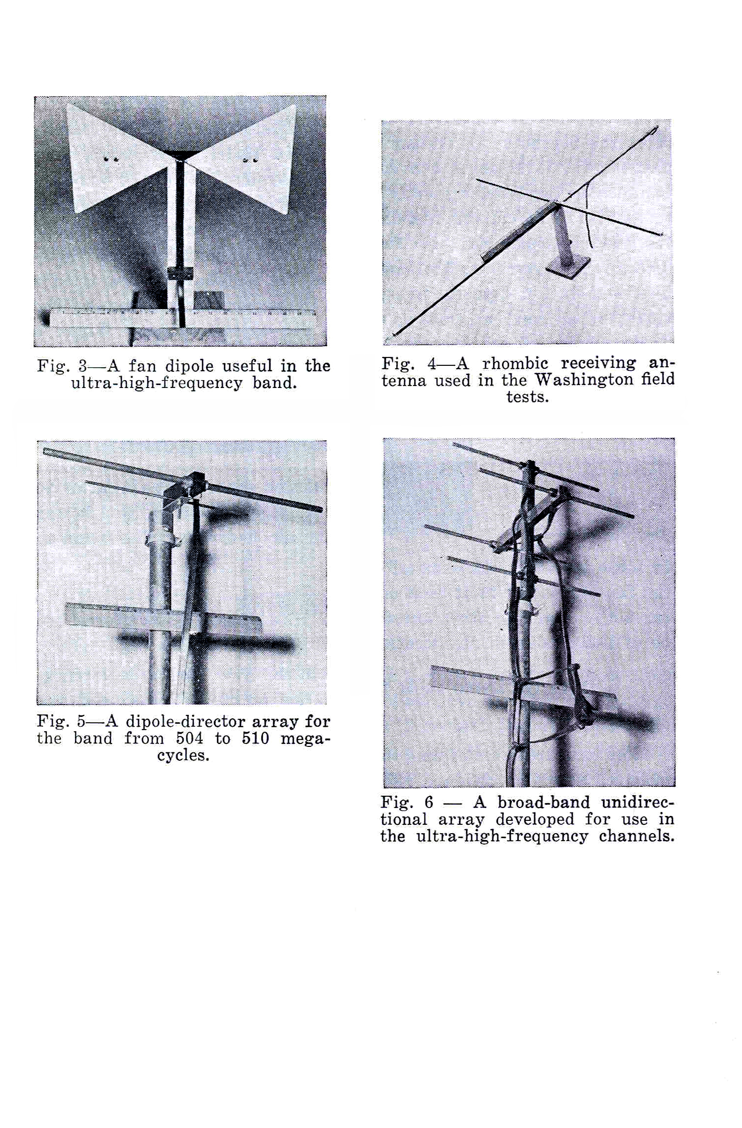
Installation of converters and receiving antennas started
shortly after the beginning of transmissions on September 1,
1948. During that month, 35 Model A converters and 16 Model
B converters were installed in the Washington area. Of these
installations, 47 were accompanied by an antenna
installation, which appeared to be appropriate for the
particular set of circumstances. These included 3
dipole-director arrangements, 5 broad-band unidirectional
arrays, 15 rhombics, and 24 fan dipoles. In each case, the
installation crew tried a variety of antenna positions and
well as the various antenna types. The predominance of the
fan dipoles was due to two factors. Where a satisfactory
picture could be obtained with the fan dipole, it was
selected because of its simplicity. In many other instances,
particularly in the shadowed areas, it was often found that
the fan dipole gave at least as strong a signal as the
directional antennas. The rhombic antenna often gave results
superior to any other type and was used in those instances.
In some of the shadowed areas it was inferior to the fan
dipole, but in at least one extremely obstructed position it
was far better than the other antennas. The dipole-director
was found to be of little value in any location.
Pictures of the different
types of antennas that were used in the test are shown
below:
|