|
|
 |
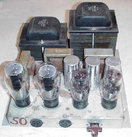
Philco Color Restoration
After 50 years the set has come alive. On March 15, I gave in to the urge to finally find out if the CRT in this set was still good as nearly all CRTs of this type have lost vacuum due to the mechanical seal that was used. I assumed the electrolytics in the power supply were shot, I tested them anyway and I wasn't disappointed as all three were bad. Everything else in the supply was in good condition |
|
|
|
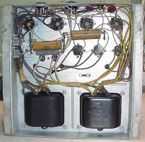
The power supply after replacing the three electrolytics with NOS units. The power supply uses two transformers, the large one supplies all the high voltage (750vac, 525vac, & 350vac), the smaller one supplies the filament voltages, three 5vac windings for the rectifiers, and two 6.3vac windings for the CRT and chassis tubes. Only the HV transformer is fused. There is a selenium rectifier that supplies the negative 200vdc. |
|
|
|
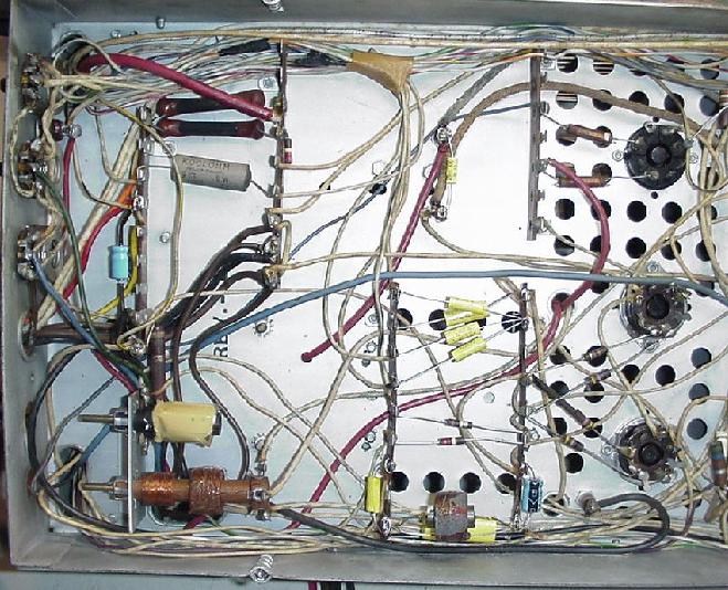
The underside of the deflection chassis after recapping. Because most of the original capacitors were molded "black beauties" I was not able to re-stuff them with the new units. |
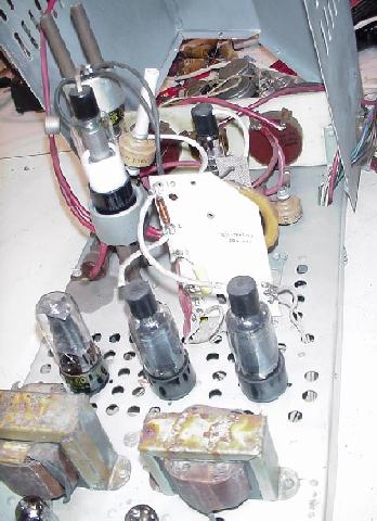 |
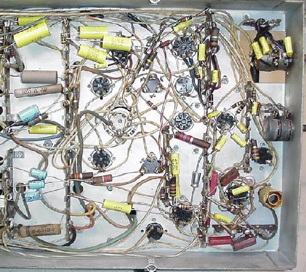
The HV section with the protective cover removed. A 6AU4 damper, the two special 6BQ6GT's, two 1B3's in a voltage doubler for HV, and a 1X2 for the focus voltage. |
|
|
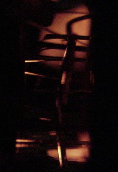
This is the glow of the CRT filaments. After finishing the power supply, I hooked the CRT filament to a variable AC supply to check the filaments. It made my day to see the filaments glow without vaporizing. After this test it was time to bring the set up and see if I had a winner or a loser. |
|
|
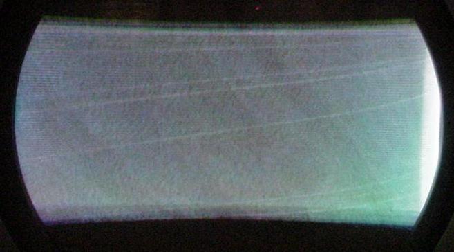
After replacing the three HV rectifiers, it came alive! It isn't much to look at right now, but it's enough to know I have a winner. Those are faint horizontal sync bars floating in the background. |
 |
The first picture after recapping the set. |
 |
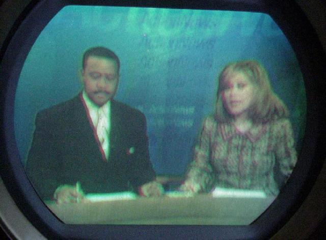
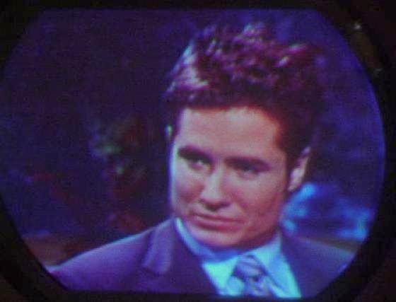
Another picture from initial turn-on. The convergence is off. My camera just doesn't take a good screen picture. |
 |
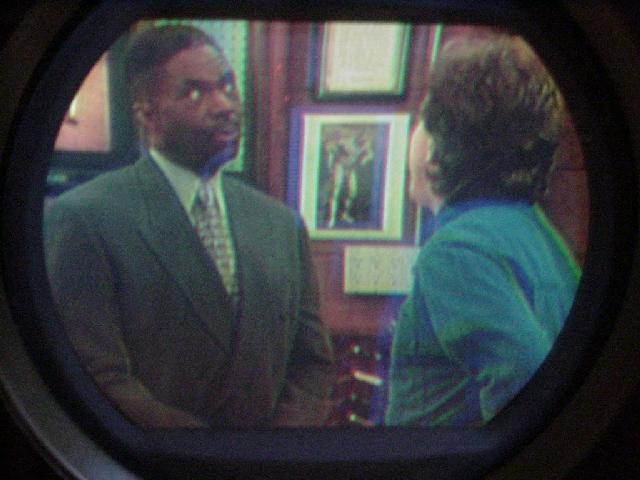
After making a lot of adjustments and tweaks. Looks much better in real life. Still need to degauss the picture tube and clean up the purity and tweak the convergence. Then try to get a camera that will do the screen justice. |
During the final restoration work the high voltage regulator went bad. This caused the HV to drop down to only a few thousand volts and caused a load on the HV supply. I have not been able to locate a replacement unit. The unit was made by Victoreen and is called a Corotron tube. It is a corona discharge device and regulates the HV to about 20KV. I'm on hold for now until I find a replacement. |
A new
voltage regulator was acquired, and the HV supply is back at
21KV. With this back in operation I was able to finish the
repairs to the AGC circuit. The set was demonstrated at the
2nd TV Convention in Hilliard, Ohio on April 24th. I decided
to leave the set at the museum so it could be seen by more
collectors than being buried away in my collection.
|