|
|
Rebuilding HV Condensers
I've recently started the restoration of another RCA TRK-12 TV, everything was going along smoothly with replacing all the capacitors and out of spec resistors until I got to the HV power supply. On the previous TRK sets that I have rebuilt, the two HV condensers which are oil filled .03uF @ 7500VDC units, were in good physical condition and when under load worked fine. These two had to be a problem, they were leaking oil. I looked for a way to just connect replacements under the chassis, but because the condensers extend under the chassis they are used as terminals for parts of the focus resistor string.So I decided to try rebuilding them (sounded like a good idea at the time). What follows is a step by step procedure to get them apart, work with some real NASTY stuff inside, and then put modern HV condensers inside. |
|
|
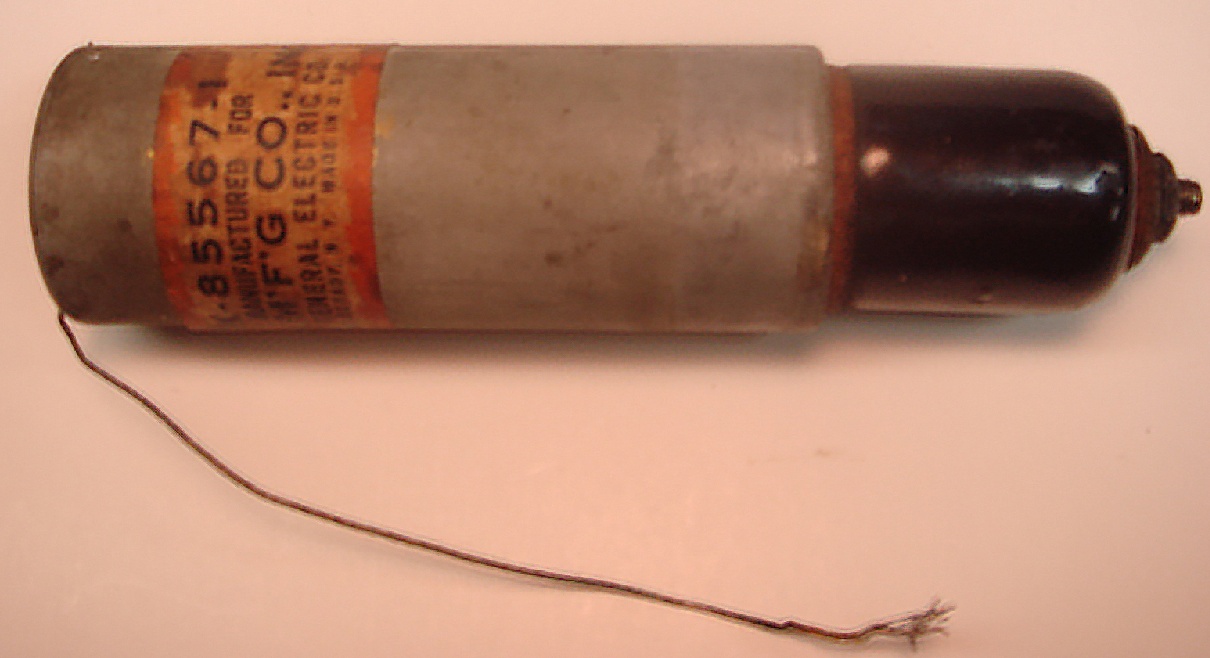
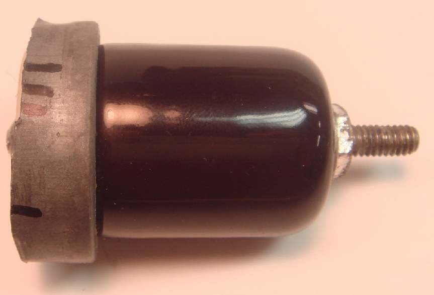
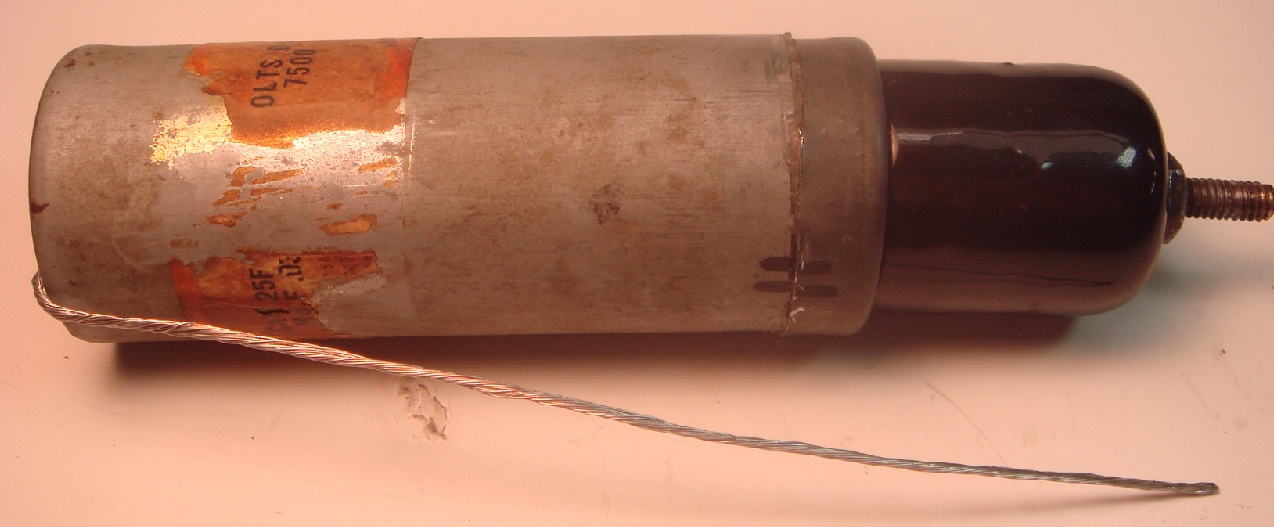
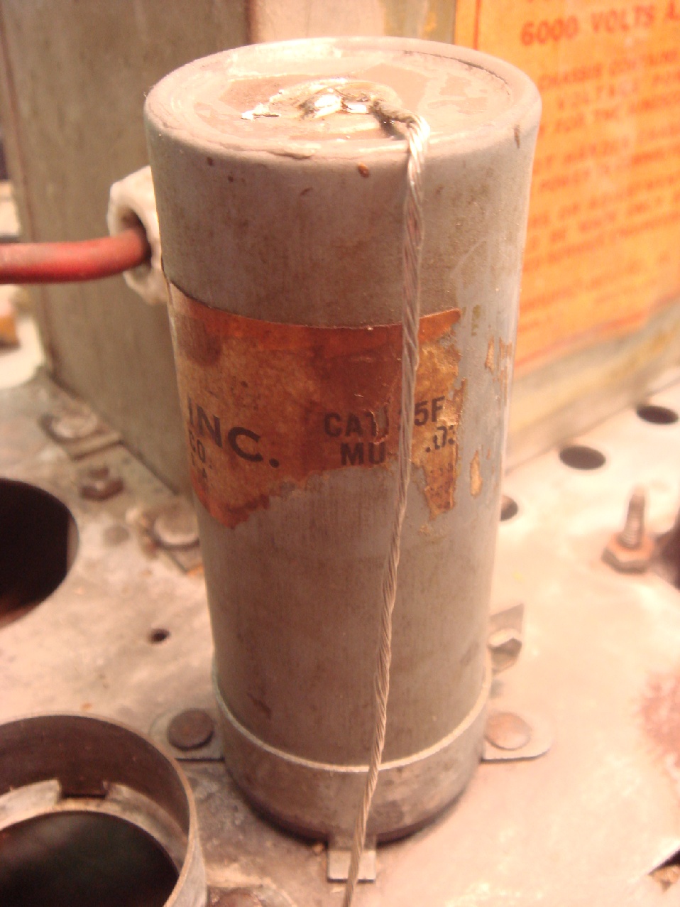
This is the original condenser, the connection on the right extends below the chassis and is used as a terminal point for the focus resistor string, the ground connection is soldered to the top of the can and connects to the chassis. The gaskets which were meant to keep the oil in are made of cork, but now are like rock and leaking. |
|
|
|
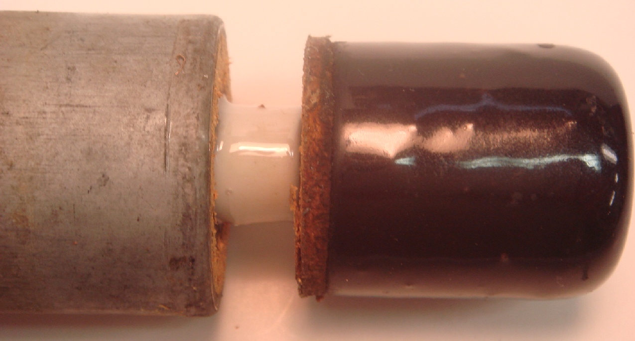
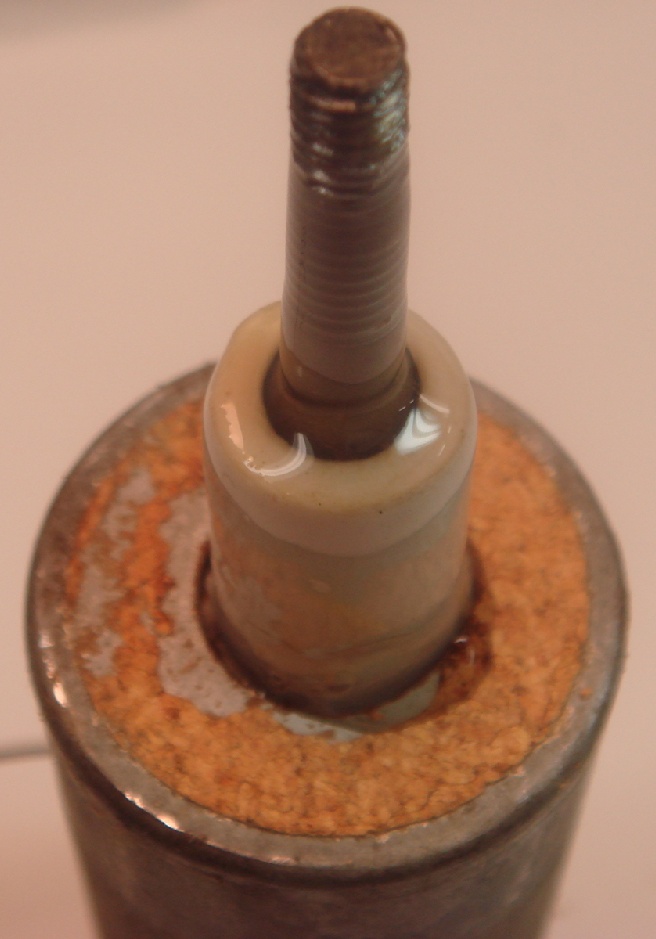
When I loosened the insulator from the can the oil started to leak out of the body as the internal gasket around the ceramic insulator had failed. |
|
|
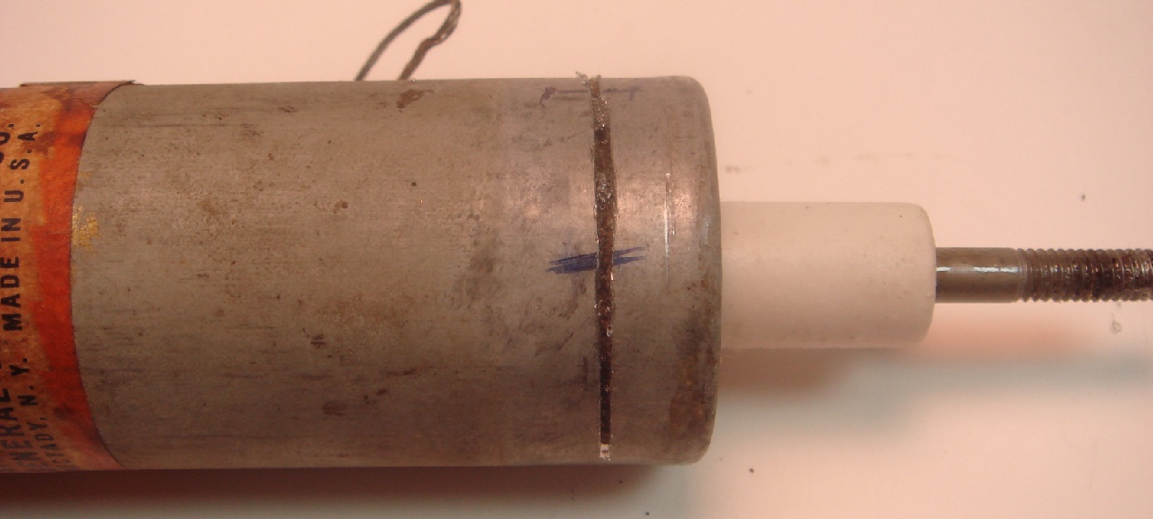
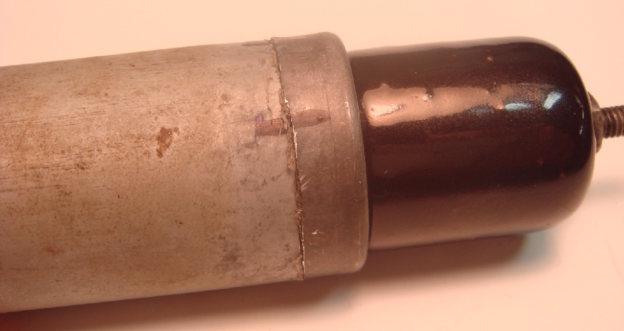
The first step in rebuilding the condenser is to open it up. The condenser is attached to the chassis by way of a conventional condenser mount that secures the can around the circumference. I made the cut through the can at this point, so the repair will not be noticeable when re-mounted. The cut is made with a common hacksaw, put some tick marks along the cut so it is easier to re-align the parts during re-assembly. Cut as quickly as you can, as the oil will start to leak out if you don't. It's a good idea to lay the can on a rag or some other material to catch any oil that leaks out while making the cut. |
|
|
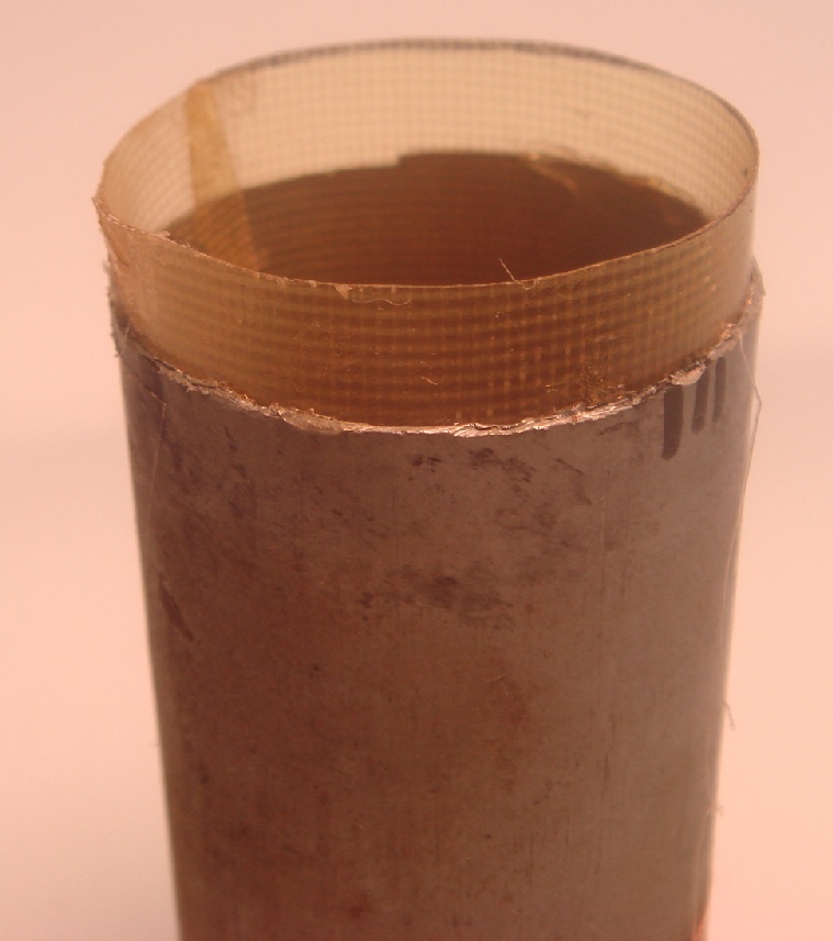
After the cut and if you are careful, this is what you will have. An open can with some very NASTY stuff to get rid of. This document isn't going to tell you where or how to get rid of this stuff, just get it out and clean the can and parts of all traces of the oil. I used something called Lac-Off to clean the oil off everything then Naptha to clean off the Lac-Off residue. I would recommend using gloves, and lots of rags or paper towels during the cleaning procedure. |
|
|
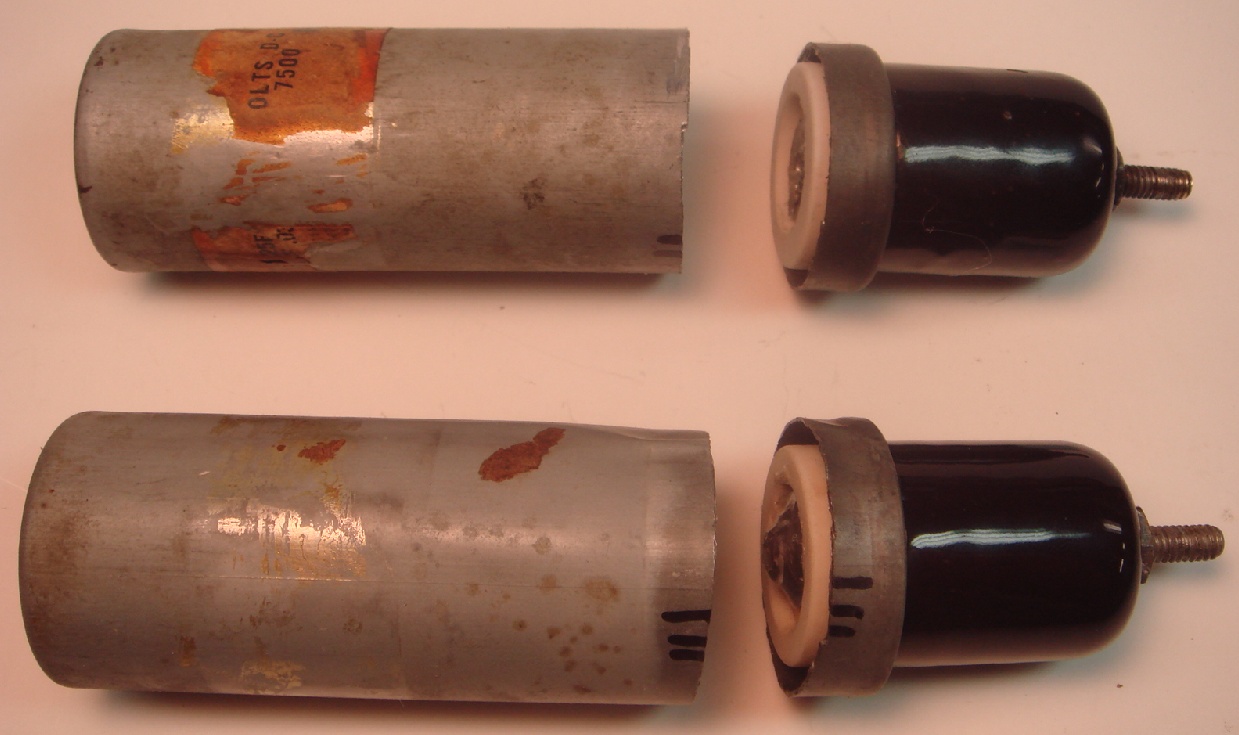
After removing the majority of oil, and cutting the foil leads to the top section you can easily remove the condenser body from the can and dispose of it. |
|
|
|
Next remove the insulating paper from the can and the small cut off section, it will be replaced during the re-construction by a HV fiberglass sheet. The main can paper insulator is easy to remove by sliding a small screw driver between the can and the paper and twist it away, then grab the paper with needle nose pliers, twist and pull out and discard. Use a small screw driver or pick to remove the paper from the small section being careful not to deform the wall of the can. Press the threaded rod out of the ceramic insulator and then press the ceramic insulator out of the small section of can. You may have to soak this piece in solvent to get the parts to release. Once everything is apart clean thoroughly in solvents. |
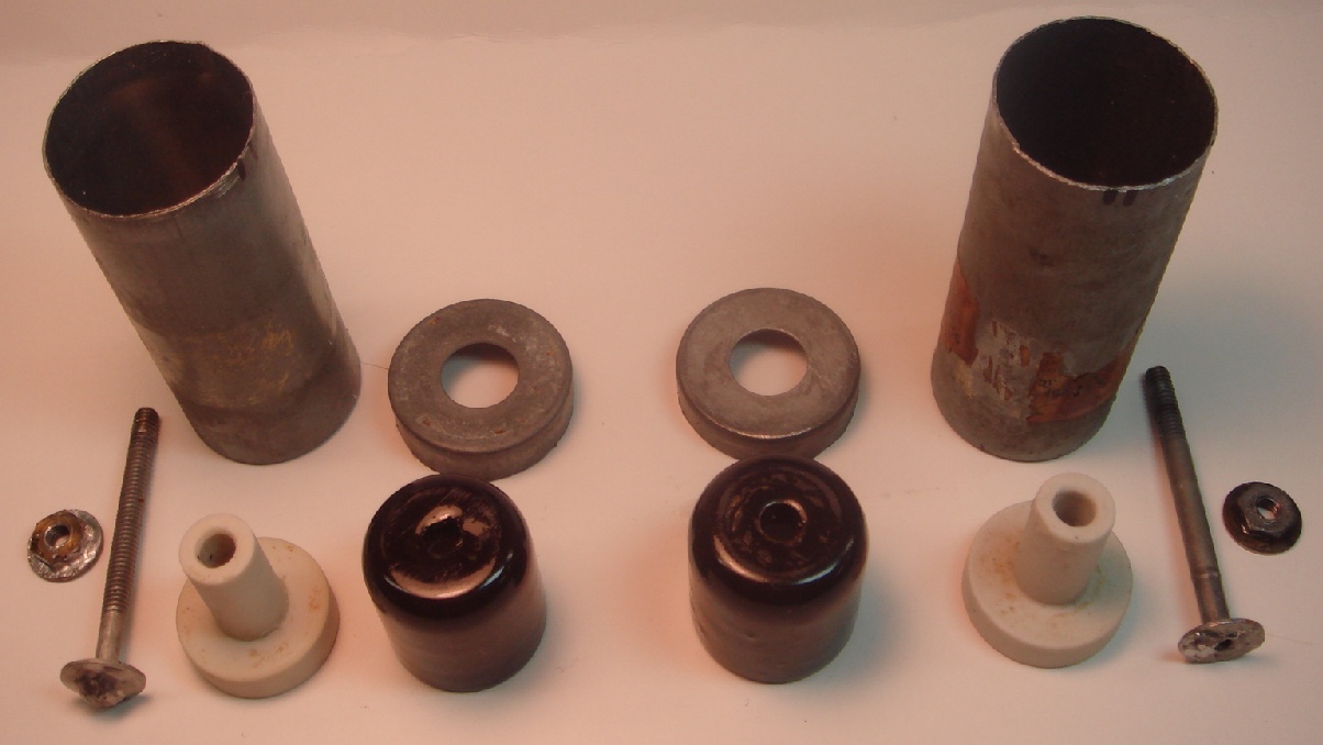 |
Components cleaned of all traces of oil and ready for assembly. |
|
|
|
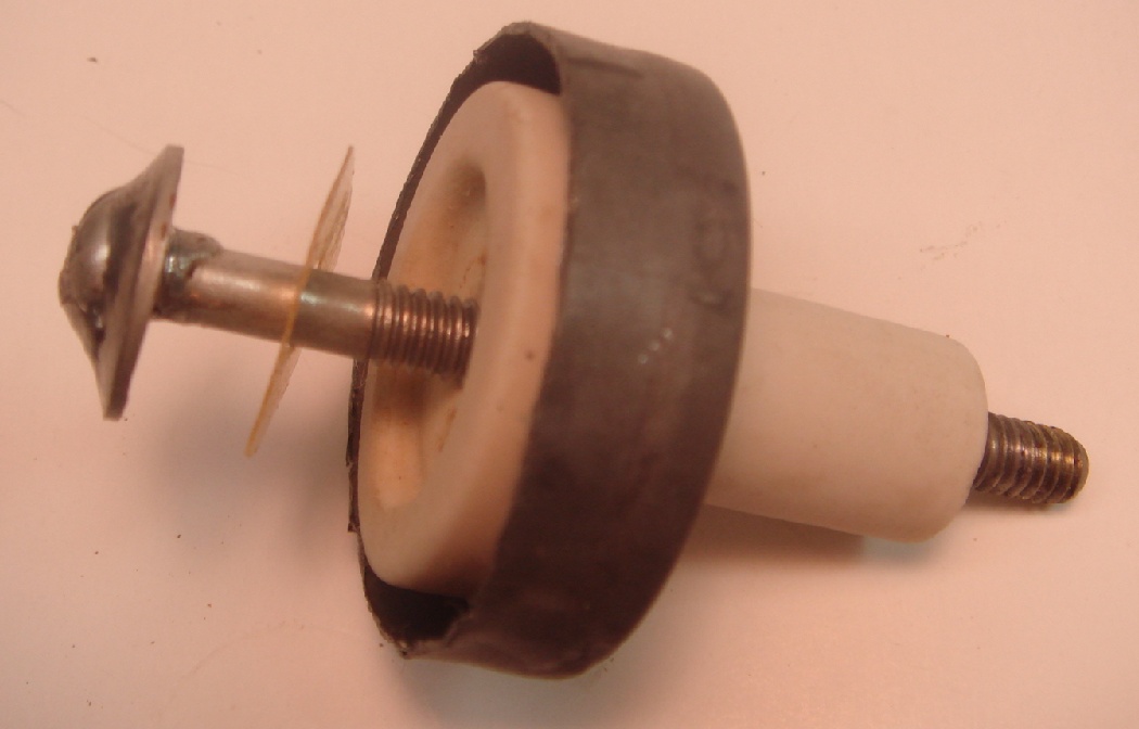
The insulator is re-assembled with a small amount of hot glue between the ceramic and the can section. I cut a small piece of HV insulating fiberglass as a washer between the stud and the ceramic. The complete insulator assembly is held together by compression of the end nut. Index marks to help with reassembly of the can will be hidden under the clamp. |
|
|
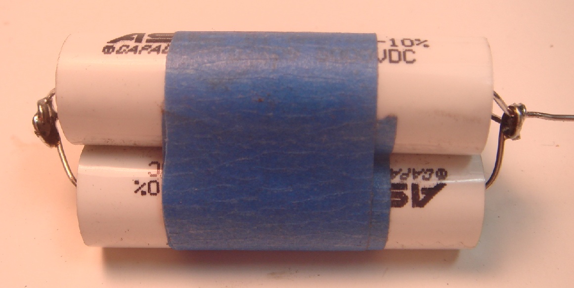
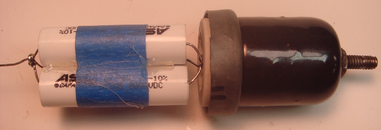
Ready for installation of modern replacements. I will be using three .01uF @ 8,000VDC units in each can to come up with the required .03uF. |
|
|
To make up the required .03uF @7500V unit, I connected three .01uF @ 8000V units in parallel. The left side leads were formed into a small flat disc that would make it easier to solder to the flat head of the terminal screw. The other ends were connected to include a long single lead to feed through the hole in the top of the can. |
|
|
The new capacitor bundle attached to the terminal connection. I added a seam of hot glue to keep the capacitors tight. |
|
|
The inside of the can is wrapped in HV fiberglass sheet, the extra sticking out of the can will slip into the insulator cap piece. The fiberglass is hotglued to the inside of the can to give some support when the two sections are mated and glued together. |
|
|
Here the two sections are assembled using hot glue. After the glue sets the excess is trimmed from the joint with a razor blade. |
|
|
Here is the completed unit ready for mounting on the HV chassis. The new ground connection was made from a #16 stranded wire with the insulation removed. |
|
|
The completed unit mounted on the HV chassis, one more to go.The total time to rebuild one unit was about 90 minutes, most of that was removing the original internals and cleaning. |