|
|
|
RCA TRK-5 Restoration
The TRK-5 is my forth pre-war television, it was purchased from the relatives of the original owner who lived in a small town north of Newark, NJ. It was probably used into the late 40's as there was a repair tag dated 1946. Also the radio had extensive repairs done, the filter capacitor and most of the paper capacitors were replaced. Other than replacement tubes I didn't see any other signs of repairs done to the television chassis. More than likely when the television failed the radio was kept in playing condition, as the set is not much bigger than a comparable console radio of this period. |
|
|
|
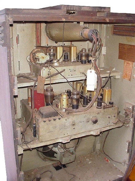
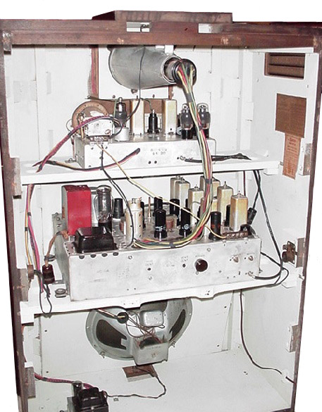
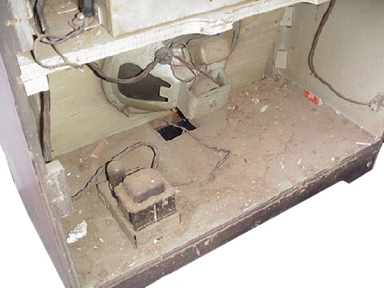
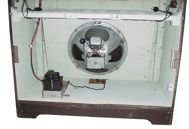
Before and after pictures of the interior of the set. Everything on this piece was covered in a thick nasty crud. The interior paint was flaking off, mainly due to moisture from being stored in a barn and that no primer was applied before the paint. There was a small amount of mouse damage to the tops of the chassis', but luckily no wiring or parts were used as food. All the wiring harnesses are hard and brittle and have to be replaced with new wires. The chassis' were cleaned with a solution of phosphoric acid, which removes the dirt and grime but leaves the chassis stamps intact. |
|
|
|
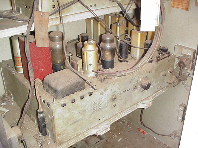
The radio chassis before cleaning and restoration.
|
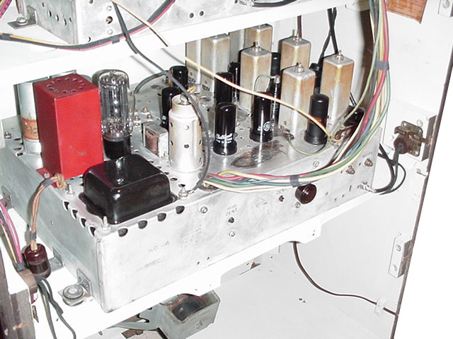
Radio chassis after cleaning and restoration
|
|
|
|
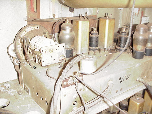
The television chassis before cleaning and restoration. |
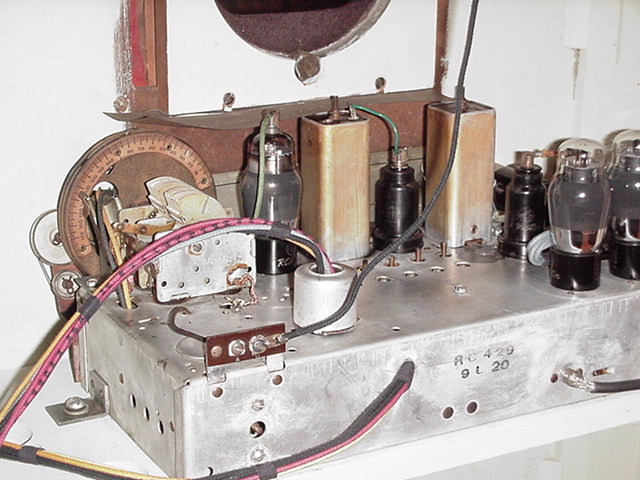
The television chassis after cleaning and restoration. |
|
|
|
Before and after pictures of the speaker and radio power supply. |
|
|
|
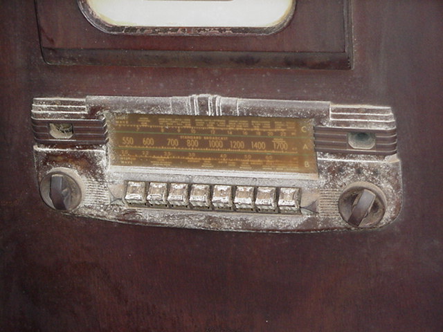
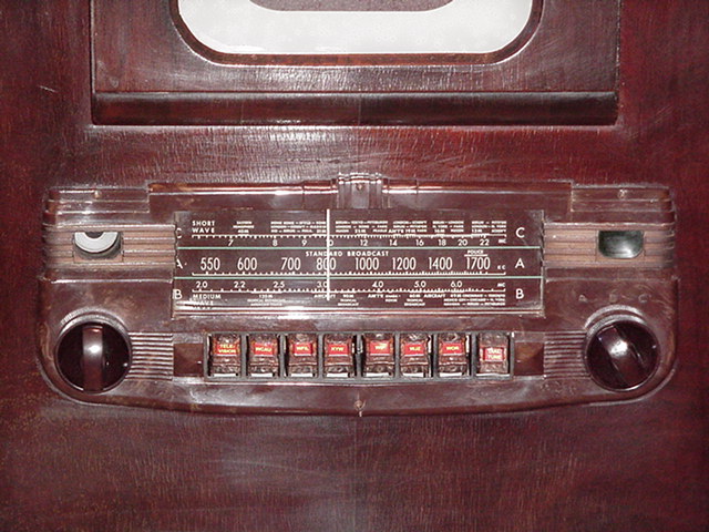
Before and after close ups of the radio bezel. I wasn't sure if the bezel and pushbuttons would be able to be salvaged as they are made of a material called "tennite" which is the equivalent of "pot metal" in the plastics world. The bezel has only shrunk a small amount and has a very small crack on the edge of the bottom center screw hole. The white crud was cleaned off with a combination of Fantastik® and plastic polish. The pushbuttons still need the call sign inserts, I need to find some originals or try to create new ones.I created the pushbutton inserts in MS Word, coloring is a little off but they complete the front.The restoration of this set has had a small setback, the power transformer HV winding shorted out during testing. I will need to have a replacement made. Before the transformer smoked, I was able to verify good video signal at the CRT and sweep signals to the CRT deflection plates.
August,
2004
|